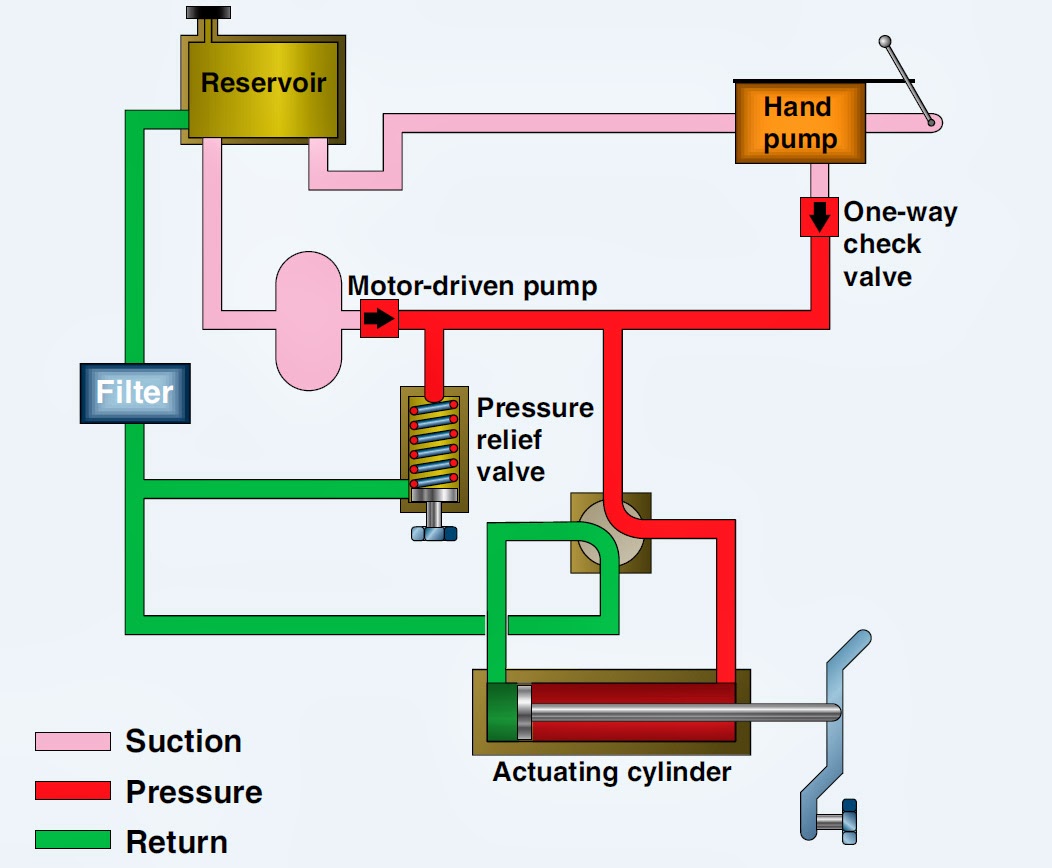
Hydraulic Flow Control Valve Schematic
How does a pressure-compensated flow control valve work? Mariners repository: hydraulics part 1 Hydraulic schematic
Directional Control Valve Basics - Part 1 - YouTube
Schematic of the electro-hydraulic valve actuation system. Flow control valves Compensated pressure non valves flow control hydraulic needle diagram schematic troubleshooting
Principle components engineeringlearn
Basic hydraulicsValve flow pressure control compensated diagram fluid work does path components simplified illustrating pressures within click enlarge Flow control hydraulic valves pressure compensated circuit symbology controlsValve directional control basics part.
Aircraft systems: basic hydraulic systemsHydraulic flow valve control 5000psi valves off Directional control valve basicsPressure compensated flow control schematic valves valve hydraulic diagram orifice.
Non-pressure-compensated valves
Way valves two valve spool control three flow four direction ports drawing pressure rotary port hydraulics machine mariners repository partHydraulic flow control valves Hydraulic schematic valve control directional drawing engineering symbol mechanical parts equipment diagram pump flow pneumatic solenoid valves conceptdraw spring reservoirPressure-compensated valves.
How flow control valves workHydraulic flow control valves Flow control valve: definition, types, components & working principleHydraulic flow control valve (5000psi).

Control valves flow hydraulic work animation valve diagram system mechanical wiring
Hydraulic basic system aircraft systems examples power gear diagram law schematic hydraulics control landing pascal components down figure mechanicalHydraulic electro actuation Flow control valve hydraulic diagram pressure compensated valves parker operation dcv reprinted 31b permission hannifin showing figure corpControl valves workings hydraulics.
Flow control valve hydraulic symbol pressure compensated diagram parker valves system way partial hannifin reprinted 31a corp permission figure .


how flow control valves work - YouTube

Basic Hydraulics - Flow Control Valves - Blog.Teknisi
-600x600.JPG)
Hydraulic Flow Control Valve (5000PSI)

Schematic of the electro-hydraulic valve actuation system. | Download

Flow Control Valves - Hydraulic Symbology 204

Directional Control Valve Basics - Part 1 - YouTube
Hydraulic Flow Control Valves - Hydraulic Repair Schematic

Non-Pressure-Compensated Valves - Hydraulic Schematic Troubleshooting
Mariners Repository: Hydraulics Part 1 - Direction Control Valves